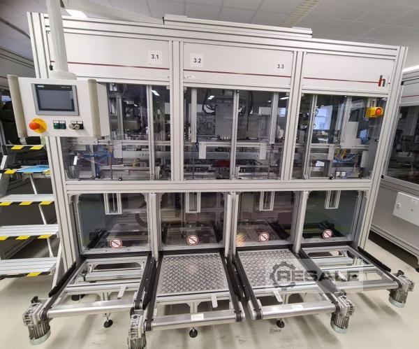
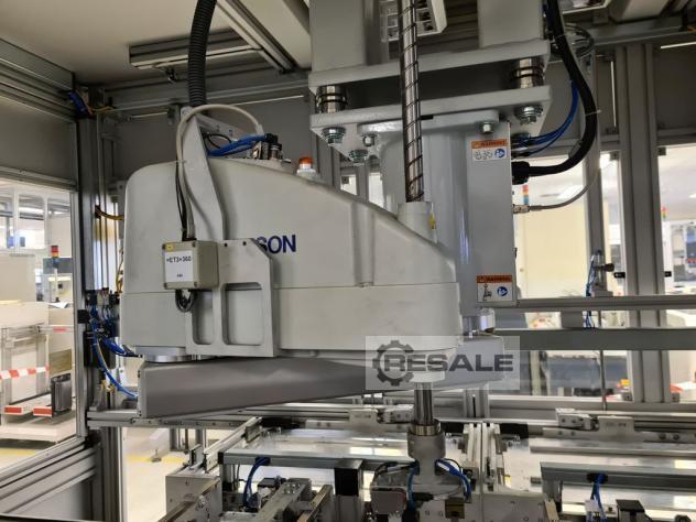
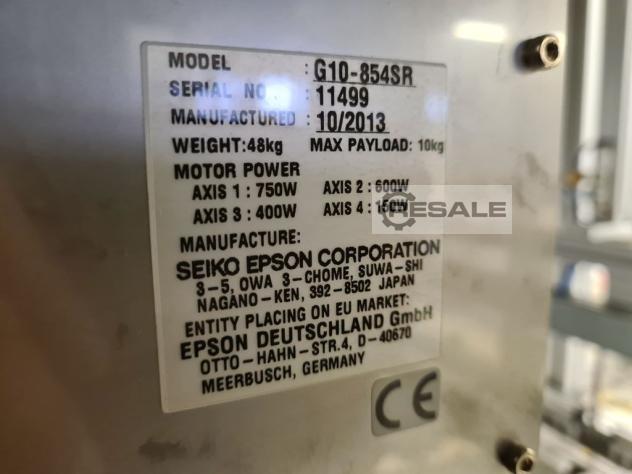
Epson G10-854SR Robot Screwdriving Station Dosing Station
Assembly of parts for car radios and navigation systems and for
testing them.
The assembly station is designed as a closed aluminium frame with a
steel welding frame inserted and has a very compact design.
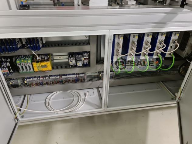
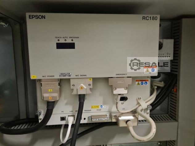
The control cabinets and valve terminals are integrated into the
system.
All movement processes during the operation of the system can be
tracked on all sides through large windows and doors.
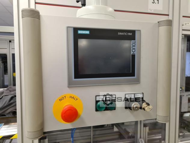
Operation is via a touch screen.
The assembly station is divided into substations 3.1 dosing area, 3.2
assembly area
KK+SW and 3.3 mounting area front. (KK=heat sink, SW=bulkhead
angle)
The work steps according to these assembly areas are described below:
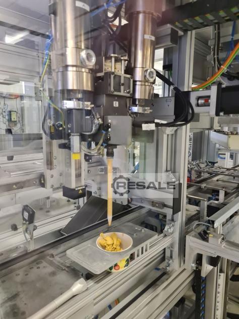
St.3.1: Dosing range
- a WT with attached chassis and printed circuit boards enters the
dosing area via the transfer belt.
- this is stopped at the stroke positioning unit (HuPo) and lifted off
the belt and fixed
- now the x-y-z handling will move the dosing head to the intended
location and start the dosing process.
- after completion of the successful dosing, the handling moves over
the rest position and the WT is placed on the belt
- Further transport to the assembly area KK+S\WV (prerequisite no WT
in assembly position)
The dosing quantity can be selected in the control of the dispenser
(Scheugenpflug) and via the PLC depending on the position
The positions can be viewed via the control panel
St.3.2: Mounting area KK+SW
- via the transfer belt, a WT runs from the dosing area into the KK+SW
assembly area.
- this is stopped at the stroke positioning unit (HuPo), lifted off
the belt and fixed, while the chassis side walls of the partially
assembled assembly are aligned
- at the same time the KK tray and SW tray positioning takes place
- a KK tray stack (12) and a SW tray stack (12) are manually placed
outside the protective enclosure on the respective infeed belt
- the two safety bulkheads are opened and the loaded tray stacks run
into the gripping position of the respective forklift
- the two security bulkheads are closed again
- the respective grippers grip the corresponding tray
- with the z-axis the tray separation and the transport upwards takes
place (over the actual height of the removal)
- for centering and tray stabilization, a centering support is pushed
and positioned under the respective tray by means of x-handing.
- with the forklift z-axis, the respective tray is placed on the
corresponding centering pad
- the trays are ready for removal of the components
- with the multiple gripper on the Scara robot, the KK is gripped in
the tray and placed in an intermediate position as an alignment aid
(in order to achieve inaccuracies when picking up from the missing
gripping position for assembly)
- the KK is scanned, grabbed again and installed on the WT if the
result of the scanner is OK
- the n.i.O. KK is stored in an n.i.O. box
- the multiple gripper on the Scara robot then grabs the SW in the
tray and places it in the alignment position
- the SW is grabbed again and installed on the WT
- continue with mounting area front
- if the provided trays are empty, they are stored on the
corresponding rejection belt
- for this purpose, the forklifts are positioned accordingly by means
of x-axes
- the empty trays are only rejected when the complete tray stacks have
been processed
- the corresponding safety bulkheads are opened and the empty tray
stacks are discharged for manual removal
- the two security bulkheads are closed again
St.3.3: Mounting area front
- the front is positioned on the circumferential WT in a separate nest
- with the multiple gripper on the Scara robot, the front is removed
from the WT equipped with KK and SW in the KK+SW assembly area
- the front is positioned in the nest of a mounting unit
- the WT runs over the transfer belt from the assembly area KK+SW to
the mounting area front and is stopped by the hub positioning unit,
lifted off the belt and fixed, while the chassis is held down
- the positioned front is joined by a rotary lifting movement on the
WT
- after completion of the successful front assembly, the assembly unit
moves to the starting position and the WT is placed on the belt
- continue > Station 4


 Germany